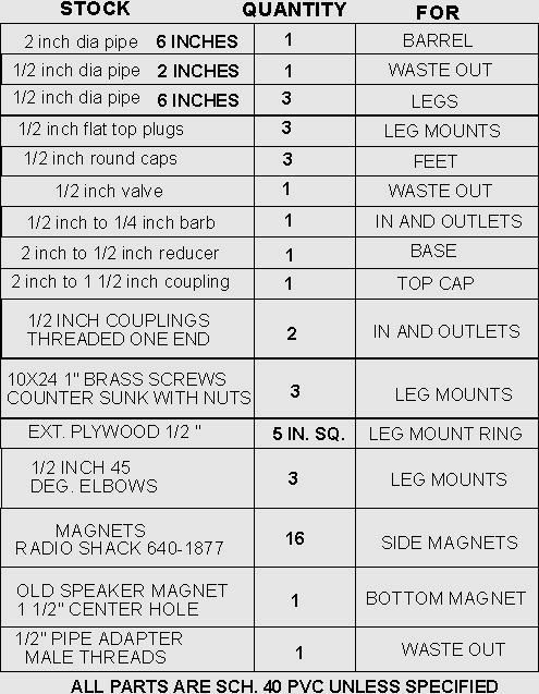
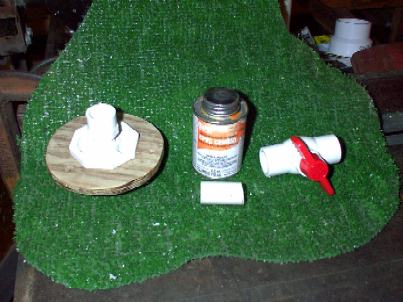
MATERIALS NEEDED
TOOLS NEEDED (Minimum)
This design is proposed for use as a secondary concentrator for M-State water that has been collected from most any primary Vortrap. It can be connected directly to the output of the primary trap, or water can be run through it later by using a funnel on the input tube and simply pour the water through. It works via a slow vertical vortex that allows the inlet water it to separate utilizing 3 forces. Gravitational forces will tend to push the oil to the top. The vortex action will cause the M-State to concentrate in the center of the tube. Magnetic shielding on the lower end of the trap and on the waste out will deflect a high percentage of the M-State particles toward the surface. The top is left clear to observe the action in the trap. You will notice that the output simply "skims" the surface water off taking the M-State substance, generally an oil, with it.
MATERIALS NEEDED
TOOLS NEEDED (Minimum)
CONSTRUCTING THE TRAP
Step 1.
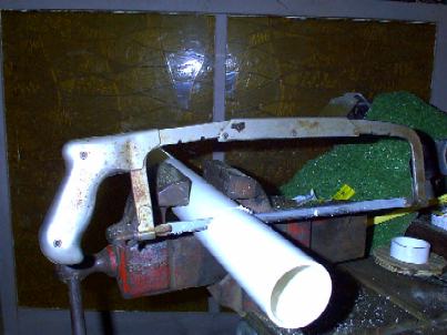
Secure the length of 2 inch diameter pipe into a vice or other holding device and cut a 6 inch piece off. Scribe a line all the way around to guide the cut if you are using a hand saw. This cut needs to be very smooth and straight.
Step 2.
Secure the 1/2 inch diameter pipe and cut the following lengths:
Cut 3 pieces 6 inches long for legs.
Cut 1 piece 2 inches long for the waste out.
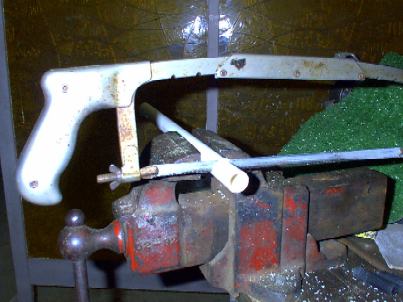
Use the sandpaper to clean off the burrs.
Step 3.
Make a leg mounting ring of exterior grade 1/2 inch plywood or acrylic sheeting. Start by drawing two concentric circles. The inside circle is to be 2 3/8 inches and the outer is to be 5 inches. Use a hole saw to cut out the inner circle if available. If not, drill starter holes as shown and use a saber saw or hand coping saw to finish the job.
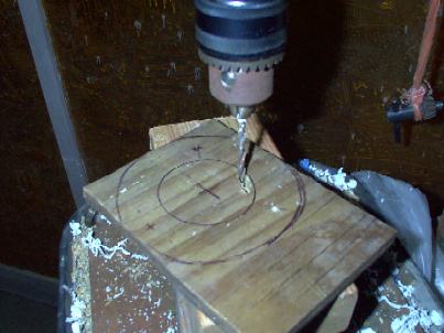
Drill the holes for the leg mount screws at this time. They are 1/4 inch in diameter and spaced at 1/3 the distance around the ring.
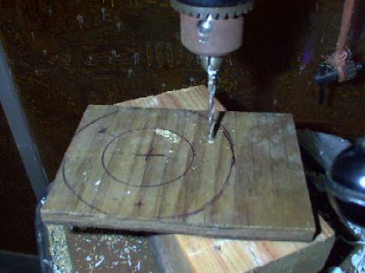
This distance is not critical. Just "eyeball " em in.
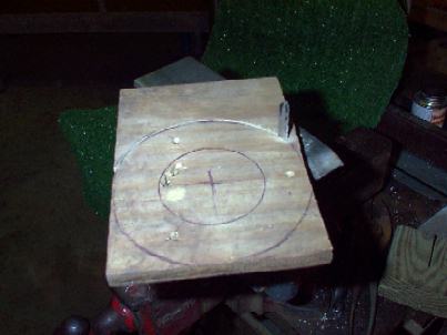
Now cut the excess material away to finish the mounting ring.
I have found a powered saber saw to be a very versatile tool especially when mounted securely in the jaws of my vice. Note: The blade is unguarded, but very visible to allow precise control and insure quality results. This is not a recommended way to use a tool, and if used this way extra caution must be exercised.
Finish the mounting ring by sanding it smooth.

The sanding block helps the sanding process, but is not necessarily essential.
Step 4.
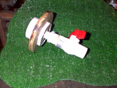
Assemble the base.
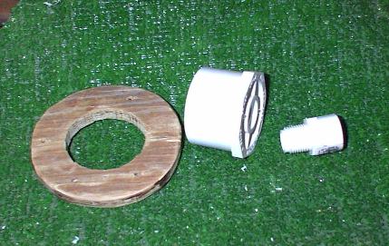
The base consists of the ring you just made, the 2 inch to 1/2 inch reducer and the threaded 1/2 inch male thread coupling. Use some Teflon tape on the threads and secure the 1/2 inch threaded fitting into the reducer. Then simply slide the mounting ring over the reducer down to the flats. A small amount of silicone sealant can be used if the fit is too loose. It is intended to be a very tight fit.
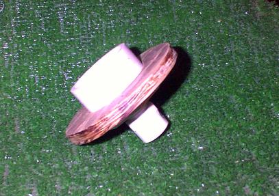
Your finished base should look like this.
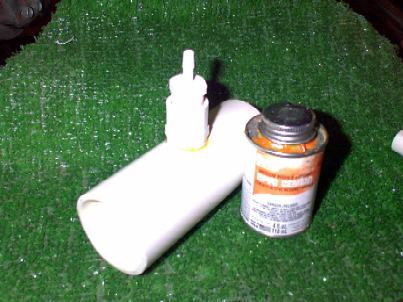
Step 5.
The outlet consists of the 2 inch piece of 1/2 inch pipe and the valve. Glue the short pipe into the valve and then glue these parts into the fitting threaded into the base.
Hmmmmmmmmmmmmmmmm!!! While straight cuts are generally desired I seem to have been near blind the night I cut this center piece. O well, it works.
Your assembly should now look something like this.
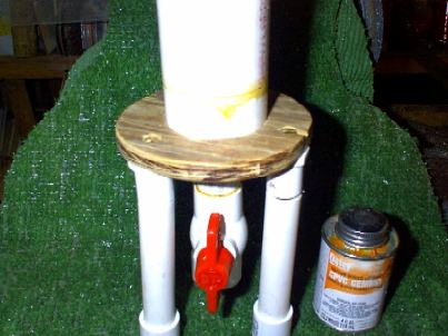
If you have an old speaker magnet you can put it on just above the valve below the base. I have some coming and will install them later. I also intent to provide additional photos when this is done. (The author)
In operation, the valve will be turned nearly "off" to allow a trickle of water out. If you want to spend the money for a small brass needle type valve and fittings here feel free to substitute them. This valve cost about $2.00 and glued quickly in place. Adjusting it is a bit touchy though not difficult.
Step 6.
Install the leg mounts. The leg mounts are 1/2 inch diameter flat topped plugs. They are hollow. They must be drilled before use. Drill a 1/4 inch hole in the center of each.
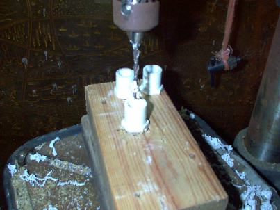
Be sure to hold these with a pair of pliers or clamp. The drill bit may tend to stick and turn them unexpectedly. If a hole is slightly off center it will not matter. But if toooooooo far off the nut may not start on the screw you will use to secure this to the mounting ring.
Now secure the three plugs to the mounting ring using one screw and one nut for each. Tighten securely with the screwdriver. You may have to use the countersink tool to get the screw heads flush. This will make mounting the magnets easier later in the assembly process.
To start the nut on the screw, first place the nut in the plug. Hold it centered with a small "pinkie" finger. Now hand start the screw and then tighten it. Brass or Stainless screws are recommended, but common hardware will also work. Using common hardware will eventually result in rust that will show in the mount.
Now install the legs on the mounts. It is not necessary to glue them in place. The fittings will press snugly. 45 degree 1/2 inch elbows are recommended. The illustration below shows using straight couplings and bending the legs at an angle to provide a larger footprint and increase stability.
Step 7.
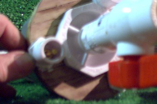
Now finish the main barrel. First drill the inlet hole. It is a 1/8 inch round hole drilled at a tangent to the side of the barrel. This is a must as it will cause the inlet water to slowly spin all the water in the entire barrel. Start the hole by aiming the drill 90 degrees at the pipe just enough to form a dimple. Finish by turning the drill to the tangent angle as shown. Mark one end of the barrel as "Top" and place this hole 4 inches down.
Note: Here is a subtle point. I drilled the hole to make the vortex turn counter clockwise. If you fill a sink with water and watch it drain it will rotate clockwise. My intent is to, again, try to make the M-State uncomfortable in the water to facilitate separation. Feel free to try holes higher, lower, and in either direction.
Drill the outlet hole. This is a 1/4 inch diameter hole 3/4 inch down from the designated "Top".
Once these holes are drilled clean off any burrs with the sandpaper.
Step 8.
Prepare inlet and outlet fittings. Because these
will be glued on, they must be shaped to the curve of the outside diameter
of the barrel. Start by cutting a very open "V" in the fittings on the
non threaded end. You may want to cut off much of the non threaded end
to shorten the fitting as shown.
Next place some sand paper on the barrel and secure it. Sand the fittings until they are the same curve as the outside of the barrel.
This is a simple process and I found it went very quickly. Just slide the fitting back and forth on the paper. Be sure not to turn it. Check the fit by placing the fitting on the pipe and looking down the line of the pipe with a light behind. You are done when you can no longer see light beaming under the fitting.
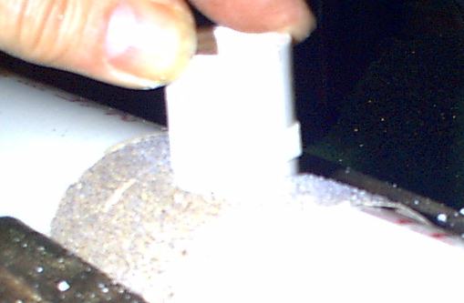
Step 9.
Install the barbed fittings into the outlet and inlet fittings and tighten them. Be sure to use some Teflon tape. Glue the sanded edges and placed one assembly over the inlet hole and the other over the outlet hole. Hold them for a few minutes until the glue sets.
To insure a tidy and strong connection do not move the part once it has made contact with the barrel.
Step 10.
Glue the barrel to the base. If the lower cut surface of the barrel is not flat and smooth place some sand paper on a flat surface and sand the edge until it is very flat with no gouges. Since this unit does not need extreme strength, this is to be a "Butt" glued connection only, While a coupling could be used here, remember, magnetic strength reduces by the square of the distance.
OOOOOOOOPPPPSSSSSSS!!!!! I SMEARED THE GLUE. #^%%&@
Note the legs. This was a prototype. Flexible rubber tubing was inside but this design did not prove stable. Use the 45 degree fittings, or straight couplings and bent legs.
Step 11.
Install your magnets. I install them by first wrapping the base with heavy duty carpet tape. This will hold the magnets in place as you position them.
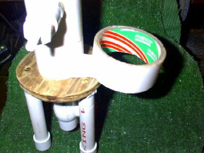
Notice it also covers up the messy (out-of-sight, out-of-mind) glue job!!! In addition, this further strengthens the glue joint and holds the leg mount ring in place. You only need one width of this tape. Cut off the roll at one complete warp and peel off the outer non sticky paper.
Now install your magnets on the tape. I placed 8 magnets with the S poles facing in. I secured these with Duct tape then placed a second row of 8 on top with the same polarity. A second wrap of Duct tape secures these in place. These can be changed at will and added to or removed for testing purposes.
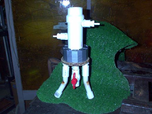
Here I used some heat and bent the legs slightly. They are mounted using simple couplings without glue. This works very nicely. You need to spread the legs for stability and to span the sink drain.
Finish the trap by shaping the 2 inch to 1 1/2 inch coupling so it will clear the outlet pipe. I did it by grinding and cutting the arc as shown above. Glue this in place once it is fully fitted.
Adjust the output valve to provide the desired flow off the top. We find good results with about half the water being skimmed off the top and the rest running out the bottom through the waste out control valve.
The top of this is open at this time, but can be fitted with reducers to pipe the escaping M-State gas to experimental collector mediums.
But, as they say,
"That is yet another story".
And my Wonderful Wife just asked those two little magic words.
"WHEN DEAR"!
HMMMMMMMMMMMMMMMM!
Build and Enjoy!
Links to Related Documents:
Building
The Winter Sink Trap V1
http://www.subtleenergies.com/ormus/tw/sinktrap.htm
M-State
Seeps Through
http://www.subtleenergies.com/ormus/tw/m-seeps.htm
Trap
Water Diary
http://www.subtleenergies.com/ormus/tw/twdiary.htm
Magnetic
Traps
http://www.subtleenergies.com/ormus/tw/magtrap.htm