The major problem with the Vortrap is that it must be used outside. This can be a real problem in the winter. In order to solve this problem a gentleman in the snow zone designed a magnetic trap which can be used inside in the winter. We call this trap the Winter Sink Trap. Following are instructions for making this trap.
Materials List:
4 INCH DIAMETER PRIMARY VORTEX SINK
TRAP PARTS LIST
ALL PARTS ARE SCHEDULE
40 PVC UNLESS SPECIFIED.
|
|
|
|
|
|
|
1.
|
4 inch dia round
|
Cut 6 1/2 inch
piece.
|
|
Body
|
|
2.
|
1/2 inch dia round
|
6 inch pieces.
|
|
Legs
|
|
3.
|
1/2 inch dia round
|
5 1/2 inch piece
|
|
Collector
|
|
4.
|
1/2 inch dia round
|
1 1/2 inch pieces
|
|
Output
|
|
5.
|
1/2 inch dia round
|
1 inch piece
|
|
Input
|
|
1/2 inch total length
|
28 inches
|
|
||
|
6.
|
4 inch end caps
|
|
Top and bottom
|
|
|
7.
|
1/2 inch polypropylene
rope
|
2 1/2 feet
|
|
Collector
|
|
8.
|
3/4 " clear vinyl tubing
|
4 inches
|
|
Waste outlet
|
|
9.
|
1/4 " vinyl tubing
|
2 feet
|
|
Output
|
|
10.
|
1/2 inch
|
Inside plugs
|
|
Leg mounts
|
|
11.
|
1/2 inch caps
|
|
Leg feet
|
|
|
12.
|
1/2" pipe to thread
Adapter
|
|
In, and out puts
|
|
|
13.
|
1/2" to hose brass
Adapter
|
|
Input
|
|
|
14.
|
1 1/2 inch coupling
|
|
Waste diffuser
|
|
|
15.
|
1 1/2 inch to 1/2 inch
reducer
|
|
Waste out
|
|
|
16.
|
90 degree elbow 1/2
inch to 1/2 inch thread
|
|
Output
|
|
|
17.
|
45 degree elbow 1/2
inch
|
|
Attach legs
|
|
|
18.
|
10 - 24 countersunk
machine screws and nuts
|
1 inch
|
|
Attach legs
|
|
19
|
3/4 inch stainless
hose clamp
|
|
Waste adjust
|
|
|
20.
|
1/2 inch threaded coupling
|
|
Output
|
|
|
21.
|
Small tube clear rtv
|
|
Leg mounts & cap
mounts
|
|
|
22.
|
Small can pvc cement
|
|
Gluing parts
|
|
|
23.
|
Roll thick carpet tape
|
|
Mount magnets
|
|
|
24.
|
Magnets - RS 640-1877
|
|
Condensing
|
|
|
25.
|
Roll duct tape or equiv.
|
|
Mount magnets
|
Tools needed: (Minimum)
Secure the tubing in a vice if available and cut off the required lengths with a hacksaw or other fine toothed blade. Hint, draw a line all the way around to insure an even cut. Use sand paper to remove burrs after cutting.
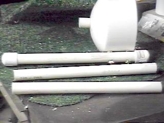
Cut the following lengths:
4 inch diameter cut 1 piece 6 1/2 inches long for the main tube.
1/2 inch diameter cut 3 pieces 6 inches long for legs.
Cut 1 piece 5 1/2 inch long for inside collector.
Cut 2 pieces 1 1/2 inches long for waste output.
Cut 1 piece 1 inch long for the hose input.
Step 2.
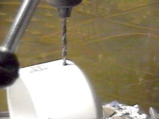
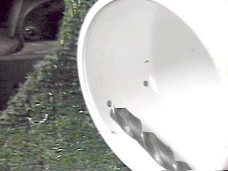
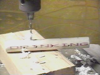
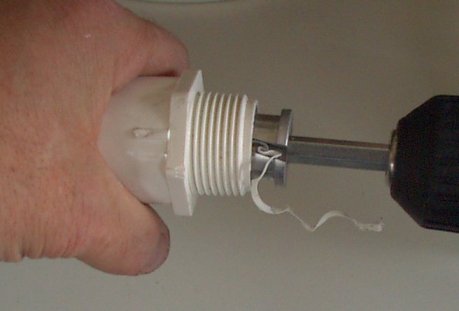
Drill the top and bottom caps as shown. This hole should allow the 1/2 inch pipe to just slide through. This should be done with a 13/16 inch spade bit or a 13/16 inch twist drill as shown. A drill press is nice but not necessary. However, you must be sure to keep the holes as straight as possible to help insure a leak proof assembly.
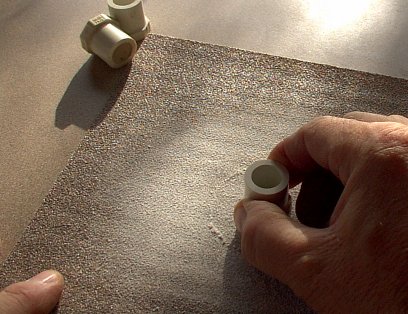
Step 3.
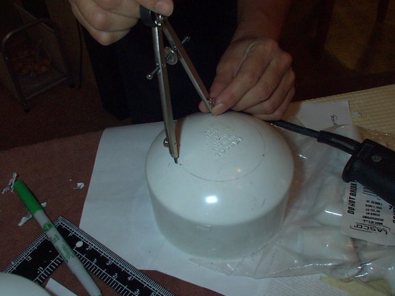
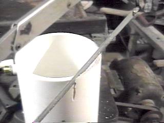
This inlet hole is to be the same size as the hole in the top, 13/16 inch. You can purchase an inexpensive spade bit for this drilling.
A woman in the Seattle ORMUS Workgroup using a spade bit.
Step 4.
Skip to step 7 if you decide to glue the
legs to the bottom.
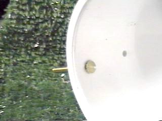
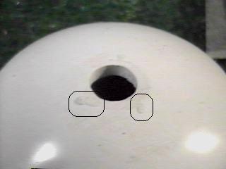
Drill the leg mount holes in the bottom cap.
These holes should be 1/4 inch in diameter. Drill three sets of two. Each set should be 1/3 the circumference of the cap. Place the holes centered 1/2 inch down from the open end of the cap and the second 1/2 inch from the rounded end start line as shown above.
Step 5.
Step 6.
Be sure the heads are below the surface of the inside of the cap or the barrel will not fit in.
Install one brass nut on each screw and tighten securely with a 3/8 inch wrench.
Continue countersinking and installing screws and nuts until all 6 are secure.
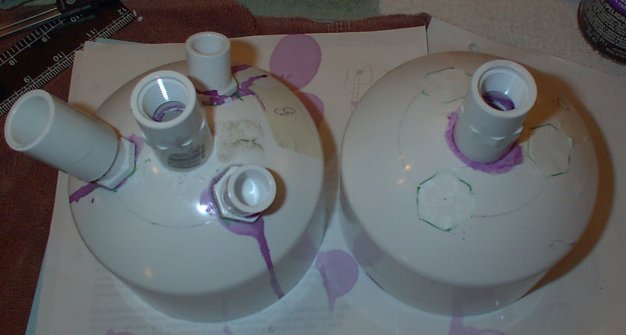
Step 7.
As an alternative to mounting the legs
with screws one can mount them to the bottom cap using solvent glue. (See
the last picture under step 10 below.)
First you must locate the center of the bottom cap.
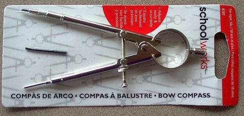
Then take an inexpensive compass like the one below.
Draw a circle with a 1 3/4 inch radius
and divide this circle into three equal
portions using the compass (set at about
3 inches) as shown below.
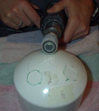
Set a half inch PVC pipe plug over a segment of the circle so that two opposing points on the plug are on the line and one of these points is on one of the three dividing lines on the circle.
Draw a line around this pipe plug.

Sand or machine the area inside the lines you just drew so they are flat.
Smooth the tops of the pipe plugs by moving
in a circular motion
on sandpaper as illustrated below.
Glue these plugs to the bottom cap.
Let the glue harden over night.
Step 8.
Step 9.
Glue the 1 1/2 long piece of 1/2 inch diameter pipe into the adapter. Do not glue the adapter to the coupling. Leaving it loose to slide up and down will allow adjusting to the sink drain.
Step 10.
Standard 1/2 inch garden hose is shown
but 3/4 inch clear vinyl is recommended. Install a hose clamp on the middle
section of the hose. This will allow you to restrict the waste outlet flow
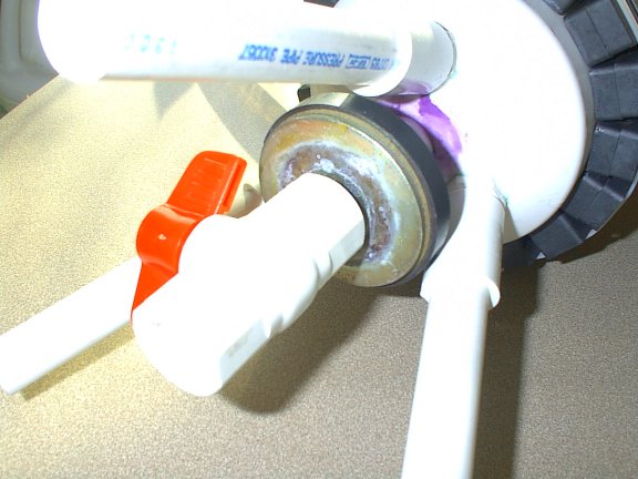
while not upsetting the vortex action. Some people prefer to use a half
inch ball valve here as this allows finer control of the volume of outlet
flow.
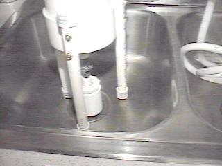
Alternative ball valve installed on the bottom of the sink trap
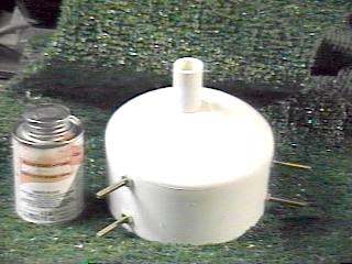
Step 11.
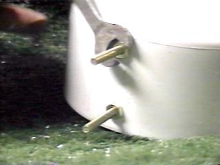
Position them on the two screws. Place a flat washer on each screw and then a nut. Also push a top and bottom 1/2 inch diameter cap on each end of each leg. These do not have to be glued on.
Tighten the nuts firmly but do not distort the pipe.
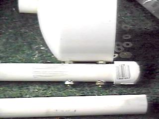
Here is a picture of the base with the three legs and output diffuser in place.
If you decided to glue the legs on you place couplers over the pipe plugs you previously glued to the bottom cap. You can insert lengths of pipe into these pipe couplers. This arrangement allows you to easily change the length of the legs to fit special situations.
Step 12a.
There are two variations for the top.
The first variation used fixed parts and you cannot change the collector
material. The second variation allows the collector material to be changed
in the event that it becomes clogged or is unsuitable for a certain situation.
Here are the instructions for the first variation.
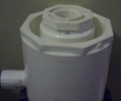
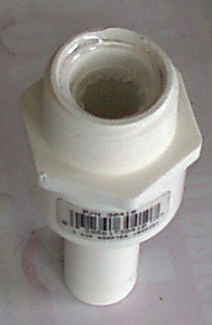
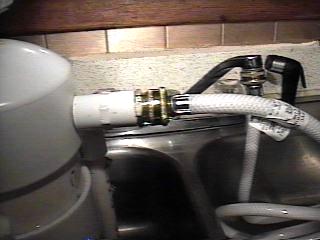
To finish the top, assemble the inlet parts.
The brass hose adapter, the coupling threaded on one side and the 1 inch piece of 1/2 inch pipe. Glue the pipe into the coupling. Thread the hose adapter into the coupling. Use some Teflon tape to guard against leaks. Finally, glue the assembly into the hole in the top cap. If it protrudes too far into the cap, use a knife and / or sand paper to bring it flush with the inside surface. It will not install if it protrudes.
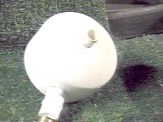
Here is the inlet after it is installed.
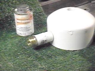
Be sure the coupling is glued flush to the top cap. This serves as additional glue area to reduce the possibility of leaks. If you need to re-tighten the inlet hose fitting be sure to hold the coupling with a wrench to avoid creating a leak in the glued joints.
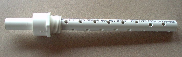
Step 13a.
Stating 1 inch down from one end drill 1/4 inch holes at 90 degrees every half inch until you reach the bottom. Clean off the burrs with sand paper.
Step 14a.
Prior to installing the collector pipe sand off any raised areas of lettering around the outlet hole. This will allow the outlet fittings to glue firmly to the top.
Step 15a.
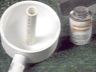
Apply glue to the top of the pipe. This is the 1 inch un-drilled end. Insert this end into the top from the inside. Push it in until the top set of holes is just below the inside of the top cap.
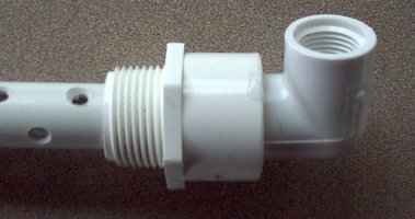
Step 16a.
Glue the elbow to this pipe. Use enough glue to insure a bond between the elbow and the cap.
Here is the finished top.
Notice the outlet barb is connected to the elbow with a coupling. This is threaded and the use of Teflon tape is recommended.
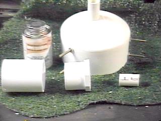
Step 12b.
This is the second variation which allows
the collector material to be changed in the event that it becomes clogged
or is unsuitable for a certain situation. The special parts for this variation
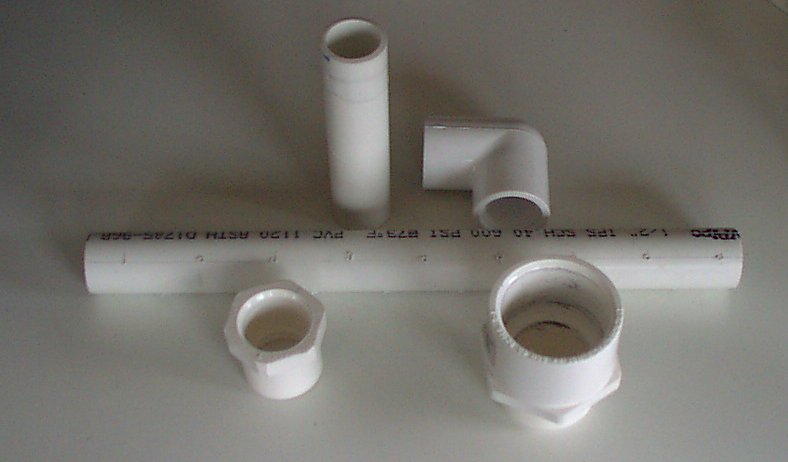
consist of:
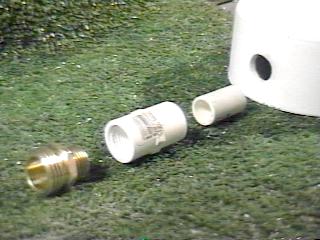
4" PVC coupler
4" slip by 2" slip reducer
2" slip by 1" pipe thread reducer
1" male pipe to 1" female slip adapter
3/4" slip to 1/2" slip reducer
10 " piece of 1/2" PVC pipe
2" piece of 1/2" PVC pipe
1/2" 90 slip to thread elbow.
Reducers and collector assembly.
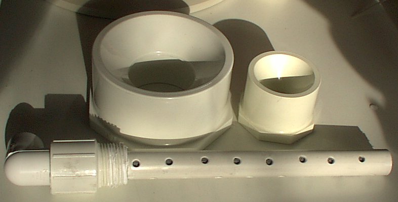
Collector parts.
To finish the top, assemble the inlet parts.
This step uses the same parts as in Step 12a: a brass hose adapter, the coupling threaded on one side and the 1 inch piece of 1/2 inch pipe. Glue the pipe into the coupling. Thread the hose adapter into the coupling. Use some Teflon tape to guard against leaks. Finally, glue the assembly into the hole in the 4 inch top coupling. If it protrudes too far into the coupling, use a knife and/or sandpaper to bring it flush with the inside surface. It will not install if it protrudes.
Be sure the coupling is glued flush to the top cap. This serves as additional glue area to reduce the possibility of leaks. If you need to re-tighten the inlet hose fitting be sure to hold the coupling with a wrench to avoid creating a leak in the glued joints.
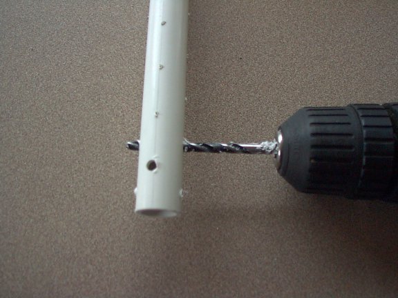
Step 13b.
This variation uses a longer (10") m-state
collector pipe. Starting 1 inch down from one end drill 3/16 inch holes
at 90 degrees every half inch until you reach the bottom. Clean off the
burrs with sand paper.
Finish the M-State collector pipe.
Step 14b.
Assemble and glue the two large reducers
into the 4" coupler.
Top cap assembly.
Step 15b.
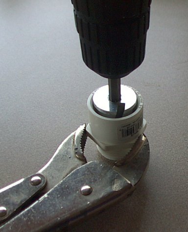
This step requires the use of two special tools. These tools are called Fitting Savers and can be found at:
I used the three quarter and half inch inch Fitting Saver to bore out the 1" male pipe to 1" female slip adapter and the 3/4" slip to 1/2" slip reducer, respectively.
Bore out the 1" male pipe to 1" female slip adapter.
Glue and insert the 2" piece of pipe into the 3/4" to 1/2" reducer.
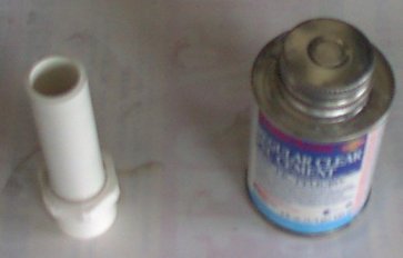
Glue and insert this assembly into the previously bored 1" male pipe to 1" female slip adapter.
When the glue has hardened, bore out the
inside of unused end of the 3/4" to 1/2" reducer to a depth of 3/8 inch.
Try to keep the drill straighter than
in the illustration.
Glue and install the previously drilled collector pipe.
Step 16b.
Glue the 1/2" 90 slip to thread elbow to this cut end.
The outlet barb will threaded directly into the elbow. As with all threaded connections, the use of Teflon tape is strongly recommended.
Step 17.
Install the oil absorbing material. This
is made of a section of 1/2 inch polypropylene rope. Fiberglass reinforced
plastic screen material can be used but it is not as safe since the glass
fibers can break off and get into the output water.
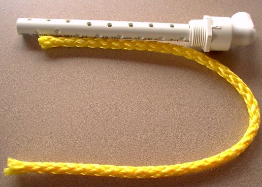
Fold the rope in two and push it into the
end of the collector pipe.
You must twist the rope as you push it
in as it is a tight fit.
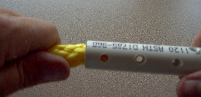
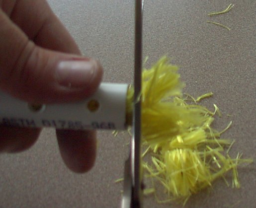
This rope should be pushed in till it reaches the pipe elbow at the other end of the pipe.
When it is all the way in you can cut excess rope off with scissors.
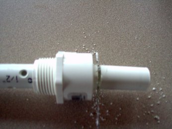
Step 18.
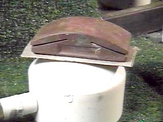
Starting this with a blade in the hacksaw frame works, but I found it easier to finish the slot with the blade removed from the frame. The slot should be about the width of three blades and not go below 1 inch down. Too far down will cause a leak because the top cap cannot cover it.
Here is the finished inlet slot.
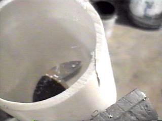
This will cause the inlet water to spin rapidly around the inside circumference of the barrel and a low pressure low speed vortex will form around the collector tube in the center.
Step 19.
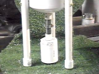
Assemble the 3 main components.
Top, Bottom, and barrel are glued with silicone sealant. This is spread thinly but uniformly on the insides of the top and the bottom caps. After the glue is applied, first push the barrel fully into the base. Next, push the top down onto the barrel. Be sure to line up the inlet slot with the inlet brass fitting. Blow into the inlet to insure the alignment is correct. Allow to set overnight before testing for leaks. Using silicone sealant will allow disassembly if necessary.
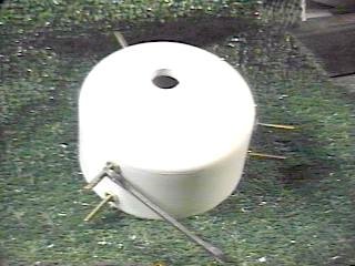
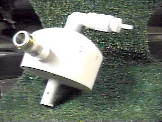
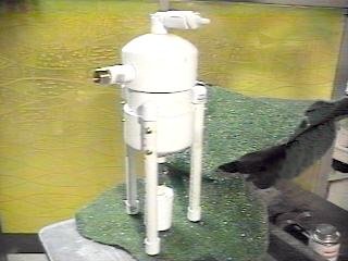
If you use the alternative top structure and leg mounting methods the finished trap will look something like this:
Step 20.
Place the unit in a sink centered over the drain. The diffuser can be adjusted to protrude down into the drain slightly to reduce splashing.
Connect the hose to the faucet. Use a hose adapter on the faucet if necessary.
Tighten both ends of the inlet hose hand tight only.
Over tightening will damage the fittings and is unnecessary.
Place the 1/4 inch clear vinyl on the outlet barb on top of the unit and route the hose back down to the drain. Slowly turn the cold water to full on. If you do not observe some flow out the 1/4 inch tube slowly tighten the hose clamp until you do see flow. With flow out the M-State out tube, you should not have any leaks at the barrel or other fittings.
Step 21.
Install magnets as desired and use the trap.
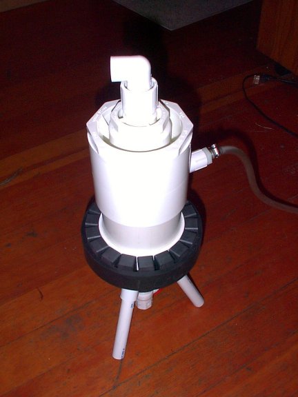
The trap as shown here has 30 magnets spaced evenly between the 3 legs. They are applied by first sticking them to a piece of heavy carpet tape. This holds them in place long enough to use the duct tape to secure them. We currently have all South Poles facing in toward the center.
Two rows were installed in this manner. A speaker magnet is placed around the waste out. Where a speaker magnet is not available several small high power ceramic magnets can be clustered around the waste out and secured with silicone sealant.
An alternative method of attaching the magnets is as follows:
Use a neoprene "bushing" as a "rubber band" to hold the magnets in place as you put them on.
First, put four stacks of magnets evenly spaced around the trap and held them in place with the rubber band.
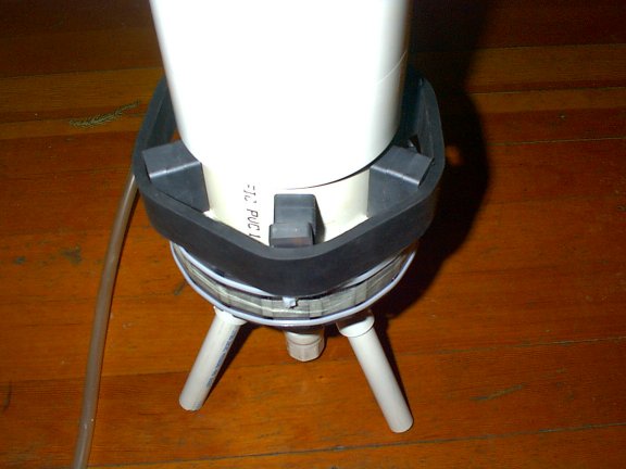
Then insert additional stacks of magnets midway between the original four. Keep inserting additional magnets till all of the spaces are filled. On the first row of magnets you can use a two magnet stack but you may have to use a three magnet stack on the second row of magnets in order to get them to put adequate tension on the rubber band.
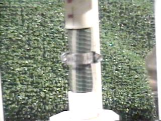
After you get all the second row magnets in place slide the third layer of magnets up with the rubber band as illustrated in the image at:
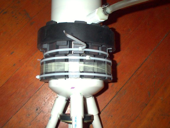
Notice that I used a cable tie to hold the magnets in place till I was able to wrap them with some fiberglass reinforced strapping tape. You can see in the first image above that I finally used a large hose clamp around the strapping tape to hold all the magnets in place permanently.
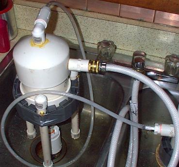
The primary trap above is feeding its output to a secondary stage trap. While this does concentrate the material more, it is not essential to obtaining good quality M-State water.
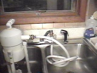
Here is a picture of the entire setup as we use it at this time.
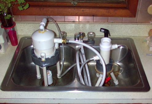
While this may look cumbersome, it is really quite easily installed and removed to allow normal use of the sink. We simply disconnect the hose from the faucet and place the entire assembly in a large roasting pan. We find it most convenient to draw about 3 gallons of water and store it in glass bottles wrapped in aluminum foil. When it is used up we draw more. This keeps the sink clear most of the time.
Here is a picture of another two stage trap setup.
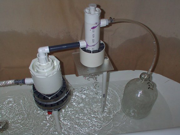
Notice that the first and second stage are rigidly connected with a 6" plastic threaded pipe nipple. This allows the use of only a single leg on the second stage trap and also provides a convenient carrying handle for the whole assembly. Since some of the attachments are not very strong I would recommend that this assembly be lifted gently and with great care.
Also note that this unit is set up in a bath tub. It is connected to the shower head through a Y diverter valve and a hand held shower hose. This allows for greater water volume through the first stage trap and means that the drip out of the second stage trap can be more rapid. A gallon usually takes less than an hour to fill.
Some Additional Thoughts
One thought I had for building the Vertical Vortex trap was to get gravity to work for us. I choose the 4-inch diameter to provide high speed at the circumference and relative quiet in the center, sort of like a hurricane. M-material seems to like quiet. The 4 inch diameter also helps to maintain a larger quantity of water allowing more time for separation before leaving in the waste-out bottom controlled drain and a much calmer center than smaller diameter tubes. Internal volume increases logarithmically with diameter.
Another benefit for a vertical indoor vortex trap is to minimize splash in the waste outlet.
If you experiment with a smaller barrel you should definitely increase the length of the barrel to help the water stay in it longer. My thoughts would be about 12 inches. In this case you would need to use 45 degree elbows to mount the legs or heat them and bend them to provide stability and span the sink drain. If you use weaker magnets you probably should stack them about 4 deep and places these stacks around the tube. The field should still be pretty strong. I have found that stacking small ceramic magnets up to 4 deep adds pull. After that the gain is minimal. I would also suggest reducing the inlet pressure with the faucet and limiting waste out with the hose clamp if your initial results are not effective. This will result in the water staying in the trap longer with a much calmer center.
While this sink trap does make a vortex, it is not exactly the same principle as the horizontal trap. Horizontal traps work on very high speed and a counter vortex in the center. The vertical design is essentially a water cyclone with the EYE in the collector material. Something to consider when building a taller trap is the need for more waste out restriction to cause the water to be pushed out the top. You would also need to make a longer collector tube for the center. The current design calls for the tube to be about 2 inches above the waste out.
I feel there is a very good chance that a 2-inch vertical trap would be effective. Personally, I would start by using moderate flow and a restricted waste out to allow a moderate vortex, calm eye, gravity and magnetic repulsion to do the work of separation. You may also consider causing a counter clockwise rotation to make the M more uncomfortable in the moving water.
Flow Rates
We have tested the flow rates for these traps and they are as follows:
Input from the sink faucet at full flow and 65 PSI in the water system.
Primary Vortrap water flow is 152 GPH.
Primary output flow to the second stage
is 10 GPH
Ratio is 15.2 :1
Second
stage input is 10 GPH.
Output is 1.9 GPH.
Ratio is 5.26:1
Ratio of Primary input to Second Stage output is 80:1.
At this ratio we get 1/2 gallon of water in about 32 minutes.
We can reduce the flow or increase it by varying the input, or the output restriction devices of either trap.
When I tested the outside horizontal vortex trap I found 200 GPH. And I had it adjusted for a flow that filled a gallon in just under 2 hours at one point. We eventually settled on about one gallon per hour. The flow of one gallon per hour produces a slow steady dribble on the output. I believe that if I procured some of the oil absorbing fabric and increased the back pressure in the primary trap we could restrict the flow to a very slow drip that would, perhaps, be a high concentration of M-oil. While the screen has shown me that it will attract oil, it does not produce any back pressure. This results in excessive flow if I try to restrict the output of the primary trap. I will continue to test this possibility when I get some of the material to work with.
Links to Related Documents:
Constructing
a Second Stage M-State Vortex Trap
http://www.subtleenergies.com/ormus/tw/stage2.htm
M-State
Seeps Through
http://www.subtleenergies.com/ormus/tw/m-seeps.htm
Trap
Water Diary
http://www.subtleenergies.com/ormus/tw/twdiary.htm
Magnetic
Traps
http://www.subtleenergies.com/ormus/tw/magtrap.htm